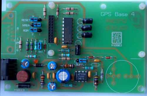
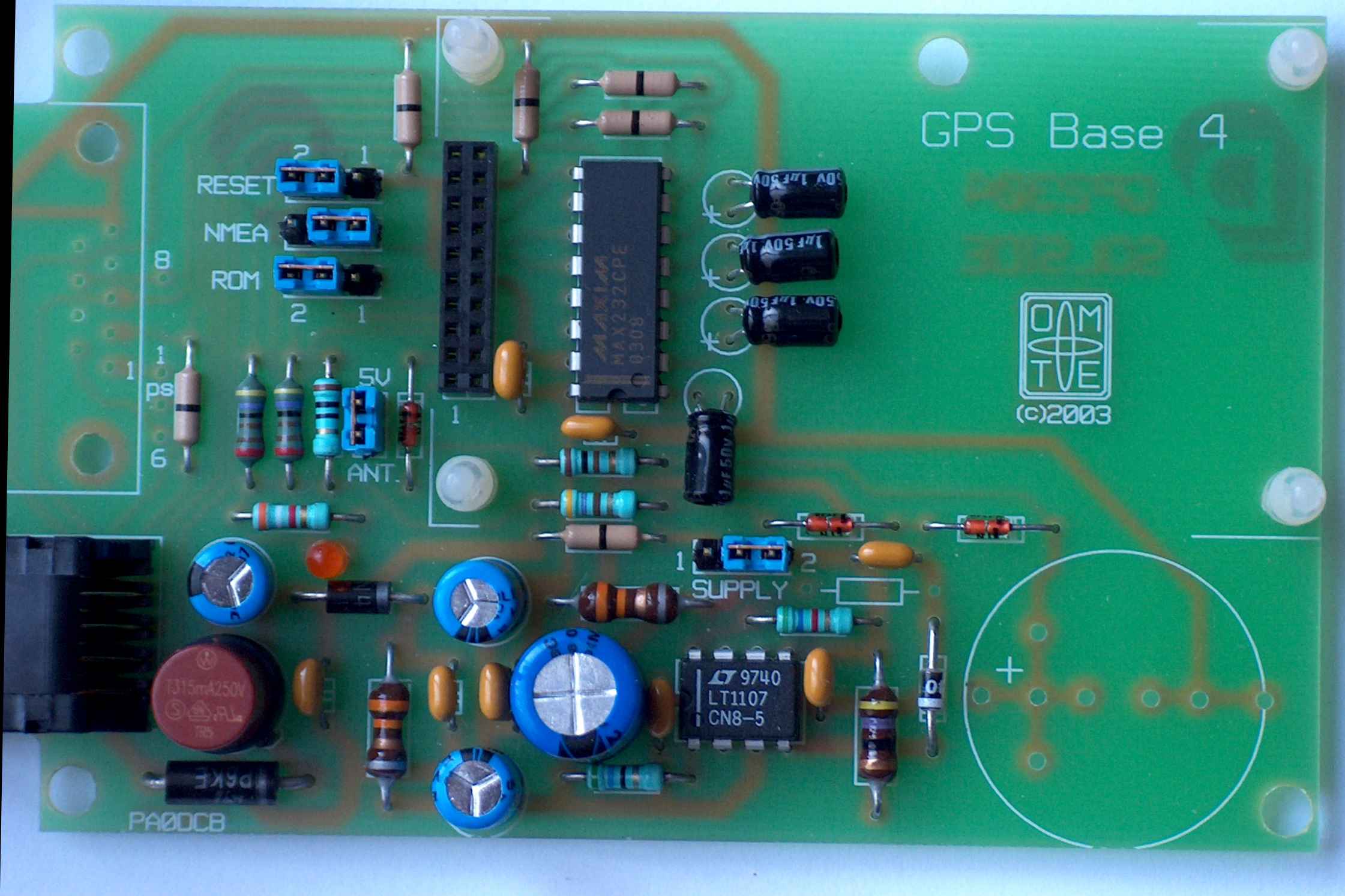
A large picture of the assembled PCB can be seen here (2200*1800, 400kB).
Building the GPS kit is not very difficult, if you have some soldering experience with this kind of projects. If you do not have any soldering / building experience, and don't know the difference between the hot and cold side of a soldering iron, i suggest you buy the kit build and tested, or buy a ready-to-use product.
A large A4 drawing of the component layout (2 times enlarged) can be downloaded here and printed.
Handle the GPS module with the usual respect for static electricity. Do not remove the module from it's antistatic bag before you really need it, and make sure your work place is not sensitive to static charge buildups.
Start with a check of the component list. These are the components Make sure you can identify every piece. For a large picture of this overview click here. The supercap (upper right in this picture) is not included, but as option available.
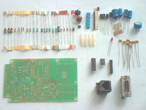
Part list GPSbase4 PCB
---------------------------------------------------------------------
count description assembly order reference:
---------------------------------------------------------------------
1 GP2304 PCB enkelzijdig
---------------------------------------------------------------------
6 Draadjumper 4E pitch
A J1,2,3,4,5,6
1 56E weerst. 4E pitch
A R2
2 4K7 weerst. 4E pitch
A R3,R4
1 100E weerst. 4E pitch
A R5
1 470E weerst. 4E pitch
A R6
1 10E weerst. 4E pitch
A R7
1 3K9 weerst. 4E pitch
A R8
1 5K6 weerst. 4E pitch
A R10 (R9 is not used)
---------------------------------------------------------------------
4 1uF 50V elco 1E pitch. B
C9,10,11,12 mount flat on PCB!
8 100nF cond. 2E pitch C
C1,2,4,5,8,13,14,15
3 47uF 50V elco 1E pitch
E C3,C7,C16
1 220uF 50V elco 2E pitch E
C6
---------------------------------------------------------------------
1 MAX232CPE
DIL 16 G U1
1 LT1107 CN8-5 DIL 8 G
U2
---------------------------------------------------------------------
2 3,3uH spoel 5E pitch B
L1,L3
1 47 uH spoel 5E pitch B
L2
---------------------------------------------------------------------
1 1N4004 Diode
4E pitch A D2
1 BYV10-40 Schottky 4E pitch A
D3
3 1N4148 sil. diode A
D5,D6,D7
1 P6KE 27A Tranzorb 5E pitch B
D1
1 LED 3mm C
D8
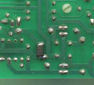
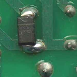
1 SMAJ 5.0A Tranzorb SMD G D4
on solderside below C6
---------------------------------------------------------------------
4 3-pin male conn. D
SW1,2,3,5
1 2-pin male conn. D
SW4
5 Shunt voor SW1-5 F
SH1,2,3,4,5
---------------------------------------------------------------------
1 T315mA Zekering F
F1
1 Zekeringhouder C
FH1
---------------------------------------------------------------------
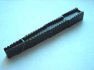
1 20 pin 2mm Female PCB conn. B Con2
1 DB9 Conn. Fem. Haaks PCB F
Con1 mounting optional
1 RJ-45 Connector voor PCB F
Con3
4 Printsteun LMSP-5-01 Richco F
---------------------------------------------------------------------
Optional extra's:
1 GoldCap 0,22F for GPS module C2
1 Antenna, active [or passive]
1 Strapu 2006 case
4 Parker 2,2 x 6,5 mm for mounting PCB
4 Ring 2,2 mm for mounting PCB
1 Antennacable with OSX/MCX connector
1 Ni-Cd or Ni-MH Accu 3V6 120mAH(max) Bat1
Tools: a bending tool, good soldering iron for fine electronics, wirecutter, pincet.
Some generic tips for building: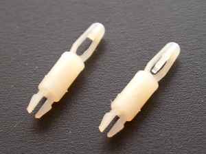
When all components are placed, check again the correct placement of the electrolytic capacitors, the diodes and IC's. Use the component layout that you can see and download above.
Also check the solder joints carefully. Especially at the 20p connector, where the solder joints are very tightly spaced.
Brush the solder side of the PCB with a short-haired brush. Small solder drops will be removed and it is easyer to see mistakes or bad solder joints.
When this is all done we can start testing the PCB.
By mounting a supercap on the GPS module, or by soldering a 3,6V NiCd cell on the support PCB the recovery time or "time to fix" will be much shorter.
The Strapu 2006 case for which the GPS support PCB was made must undergo some work
One of the case PCB mounting supports must be removed. The plastic GPS module PCB mounting support is on the same place and extends below the support PCB.
It can be cut away with a small wirecutter. Put it halfway the PCB support tab and cut it away in 2 times. Dot cut it away in one try, you could damage the case because of the high forces needed.
The GPS Support PCB is tightened with 4 small parker screw 2.2*6.3 mm with a ring.
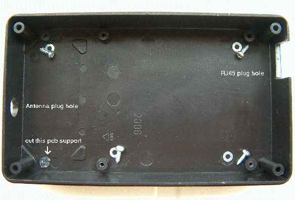
The hole for the antenne connection that is shown above, is for the situation where you connect an antenna directly through the case onto the module. If you want to make an adapter cable to for example a BNC connector in the case, the hole should be made on another place in the Strapu case. There is enough place somewhat higher on the above picture, especially when the NiCD space on the PCB is not used.
The rectangular hole on the right is for the RJ45 connector. The RJ45 is somewhat higher as the bottom part of the case, so from the cover also some material has to be removed.