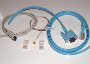
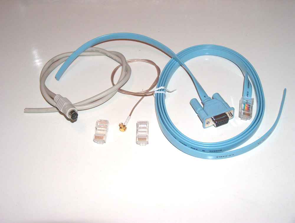
 cable kit type 1
( Or click here for a 1000*700 picture.)
For every hardware application a specific cable will have to be made. We can't think of every cable config, simply because we don't have every piece of equipment available. The best we can do is to supply as much information as we can to support you, and to share this information.
The cable kit contains all cables to connect the kit to a laptop pc. There are 2 types of cable kits, type 1 and type 2.
cable kit type 1
(
Or click here for a 1000*700 picture.)
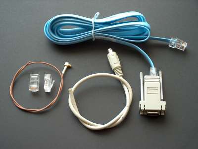 cable kit type 2
Here is a description of cable kit type 2 for use with the GPS kit
The purpose of a Y cable is to:
1 - transport the serial signals from the GPS kit receiver RJ45 connector to the
pc/laptop.
2 - supply the GPS kit with 5V tapped from the mouse/keyboard connector of the
laptop.
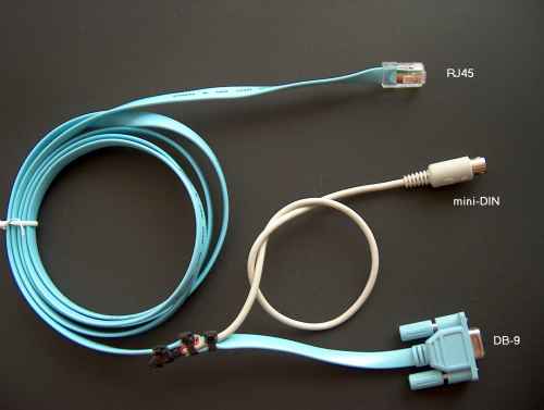
The mouse plug of your laptop becomes unusable to actually connect an external mouse, so we presume you use the internal mousepad or trackball.
What we need is:
An RJ45 connector with a longer cable to connect to the GPS kit.
A DB9 connector, female with a short piece of cable to connect to the serial
port.
A mini-DIN connector with a short piece of cable, for supplying 5V to the GPS
kit.
For this cable config we only use the bold printed wires.
| contact | direction (GPS) | level | description |
| 1 | output | RS232 | 1 PPS signal on RS232 level. |
| 2 | output | RS232 | NMEA data port output. |
| 3 | input | RS232 | NMEA data port input. |
| 4 | output | TTL | 10kHz square wave locked to GPS timebase. |
| 5 | input | RS232 | 2e serial port for DGPS receiver. |
| 6 | output | TTL | 1 PPS signal on TTL level. |
| 7 | both | ground | ground, for both RS232 port and power supply. |
| 8 | input | supply | Supply. +5V regulated or +10 to +25V unregulated, depending on pos. of jumper SW5. |
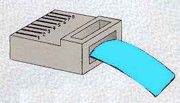
Remove the isolation over a length of ca. 4cm and cut the wires you don't need. Put a 10cm piece of 20mm thermal crimp tube over the cable to finish the cable when you are done.
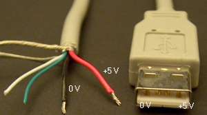
This is only used to tap the 5V power supply from the laptop for feeding the
GPS receiver.
We can't supply you with information on the wire colors - you have to find this
out yourseld by measuring with a multimeter or wire tester/beeper. The
wires we need are 3 (+5V) and 4 (ground).
Cut the cable on a reasonable length, say 25cm, strip the end, measure the wires we need and remove the other wires.
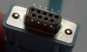
The signals on the contacts and - if you use the supplied blue cable from the cablekit - colors of the wires.
We use onle the bold printed wires in this cable.
| contact | direction (PC) | level | description |
| 1 | input | RS232 | CD (Carrier Detect) |
| 2 | input | RS232 | RXD (Receive data) |
| 3 | output | RS232 | TXD (Transmit data) |
| 4 | uitgang | RS232 | DTR (Data Terminal Ready) |
| 5 | both | ground | Common |
| 6 | input | RS232 | DSR (Data Set Ready) |
| 7 | output | RS232 | RTS (Request to send) |
| 8 | input | RS232 | CTS (Clear to send) |
| 9 | input | RS232 | RI (Ring Indicator) |
Cut the cable on a reasonable length, say 25cm, strip the end, measure the wires we need and remove the other wires.
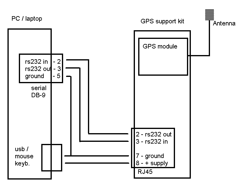
The wiring of the Y cable should look like this:
GPS RJ45 connector pin 2 --> DB9 connector pin 2 (data to laptop)
GPS RJ45 connector pin 3 --> DB9 connector pin 3 (data from laptop)
GPS RJ45 connector pin 7 --> DB9 connector pin 5 and mini-DIN pin 4 (ground)
or USB 0V
GPS RJ45 connector pin 8 --> mini-DIN pin 3 (+5V) or USB +5V
Click here to see a diagram of the cabling
Isolate the solder joints with thin thermal shrinking tube and put the larger tube over the joint.
Check the cable on correct wring with a multimeter, and also for short circuits. Put the SW5 jumper in the 5V position and connect the cable to the GPS kit, the laptop serial port and the keyboard/mouse port.
You should be able to measure 5V on the SW5 jumper, and the MAX232 ic should generate + and -9,5V. See the test procedure.
When this is all correct you can install the GPS module (after temporary removing all cables) and we should be able to see the serial NMEA data coming out of the GPS kit, for example with hyperterm (4800bd 8n1).